I haven’t posted anything for the past couple of days because I’ve been working on an exciting new project. But today, I thought, why not share an update? From now on, I’ll not only post about projects but also upload detailed videos so that you can easily build them yourself.
Today's Project: ESP32-CAM Controlled via Joystick
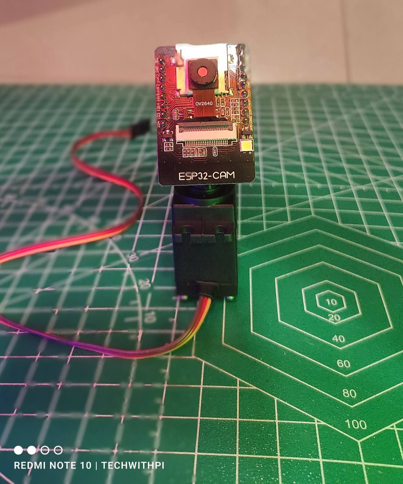
In today’s post, we’ll be controlling an ESP32-CAM module using a joystick, assigning it an IP address, and making it work just like a CCTV camera! Sounds cool, right? I hope you’ll love this project as much as I do!
Got a Project Idea? Let's Build It Together!
If you have a project idea that you’re struggling to build, feel free to DM me on Facebook or WhatsApp. I’d love to create it for you and feature it on my page—along with your name and photo! The best ideas will also get a dedicated post and video.
Join the Family & Stay Motivated!
Your support means everything to me! A simple follow from you keeps me motivated to bring more amazing content. You’re not just my audience—you’re family! Let’s grow and build awesome tech projects together.
Stay tuned for more exciting updates, and don’t forget to follow my page for regular posts like this! 🚀💡
Here’s a complete project on ESP32-CAM Servo Motor Controller using Joystick, including circuit diagram, code, and explanation.
Project: ESP32-CAM Servo Motor Controller Using Joystick
Overview
This project allows you to control an ESP32-CAM camera module’s pan and tilt movement using two servo motors and a joystick. The ESP32-CAM will stream video over Wi-Fi while the joystick moves the camera in real-time.
Components Required
1. ESP32-CAM – For video streaming
2. FTDI Programmer – To program the ESP32-CAM
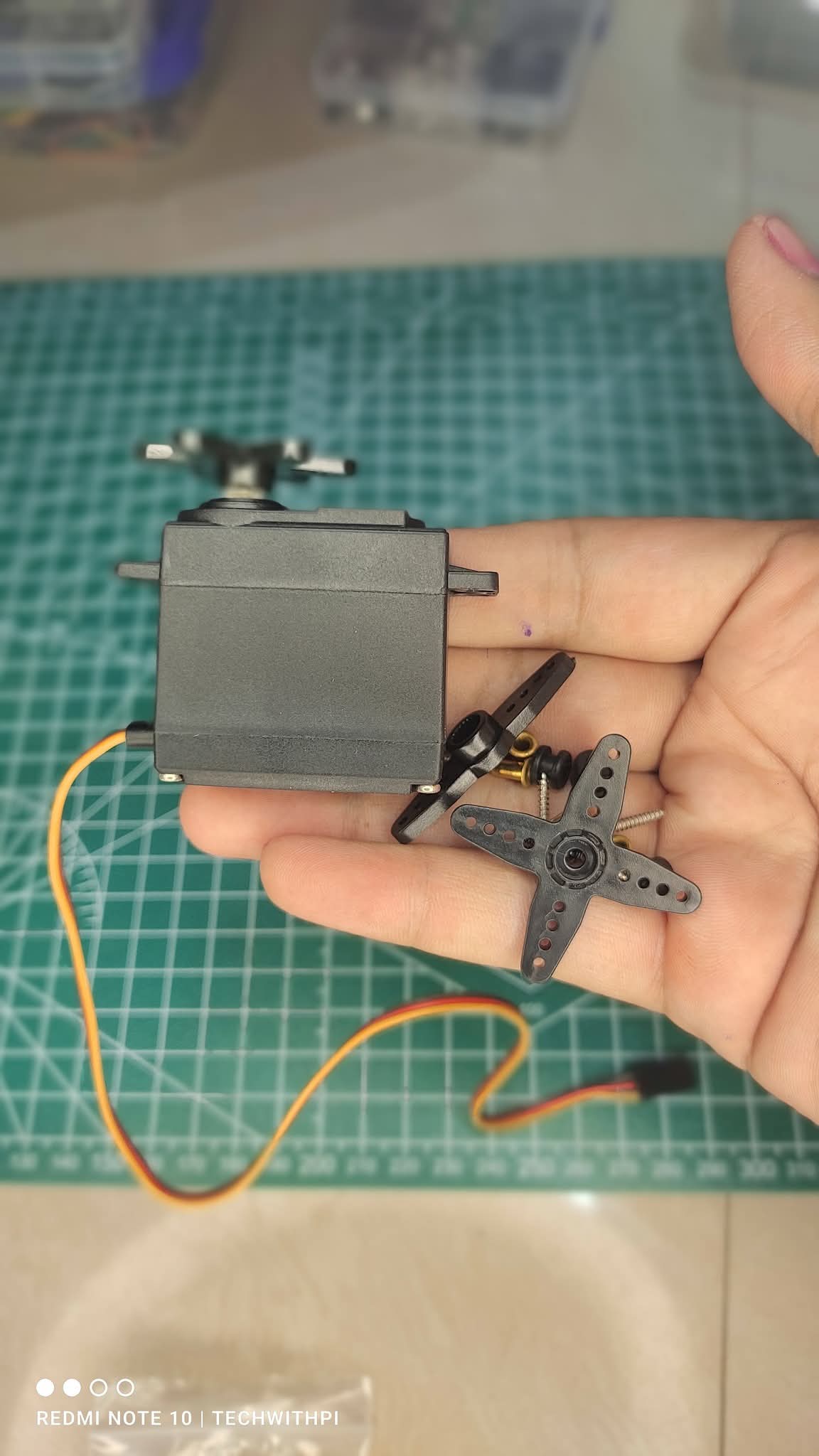
3. 2x SG90 Servo Motors – For pan & tilt motion
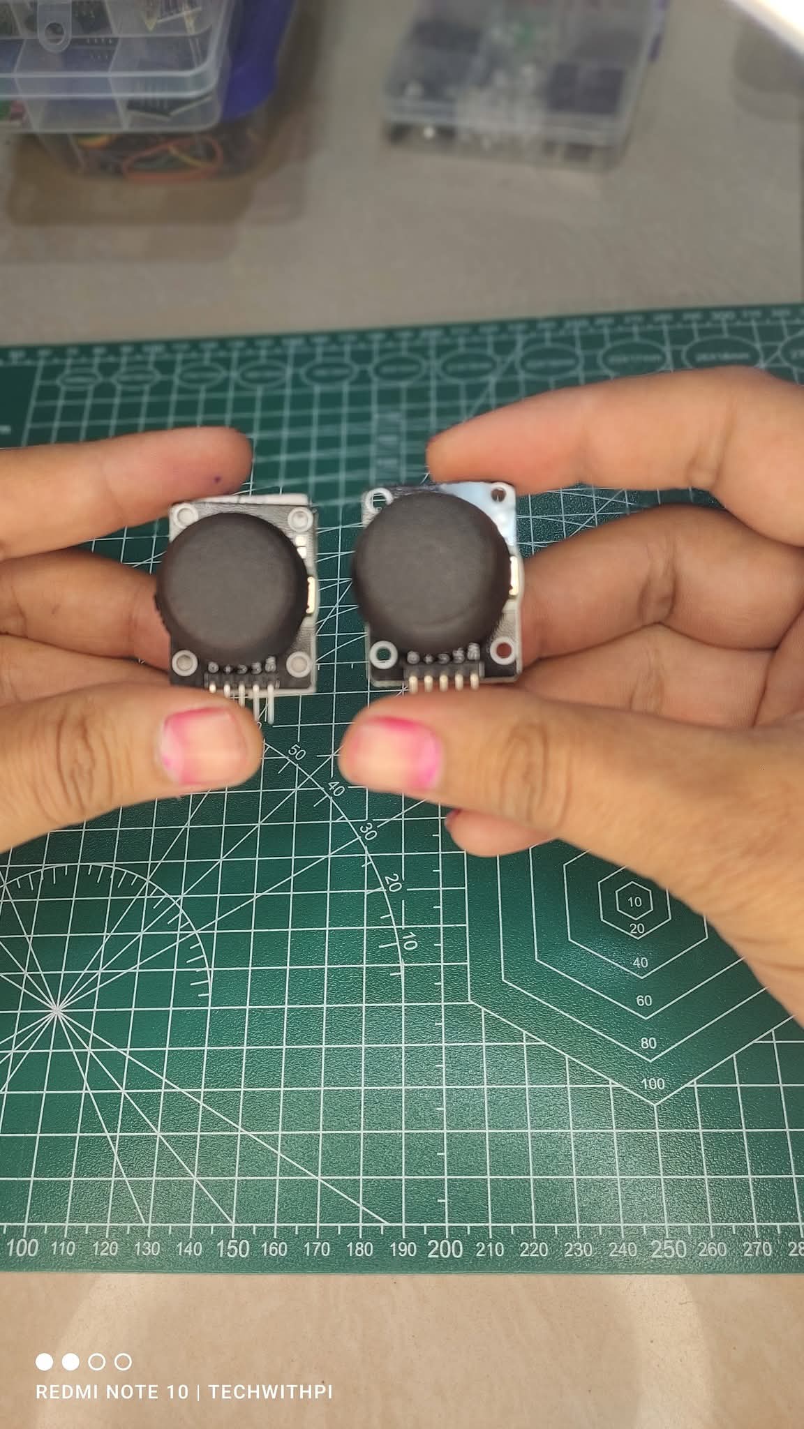
4. Joystick Module – To control servo positions
5. 5V Power Supply – For powering the system
6. Connecting Wires
Circuit Diagram
+5V GND
| |
----------------
| ESP32-CAM |
----------------
| |
GPIO12 GPIO13 ---> Servo Motors
| |
VRX VRY ---> Joystick Module
Connections:
ESP32-CAM GPIO12 → Servo1 (Pan) Signal
ESP32-CAM GPIO13 → Servo2 (Tilt) Signal
Joystick VRX → ESP32 GPIO34
Joystick VRY → ESP32 GPIO35
Joystick GND → ESP32 GND
Joystick VCC → ESP32 3.3V
Servo Motors Powered by 5V
Code for ESP32-CAM Servo Control Using Joystick
1. Install Required Libraries
In Arduino IDE, install:
✅ ESP32 Servo Library
✅ WiFi
2. Upload the Code
#include <WiFi.h>
#include <ESP32Servo.h>
#include "esp_camera.h"
// Wi-Fi Credentials
const char* ssid = "Your_SSID";
const char* password = "Your_PASSWORD";
// Servo Motor Pins
#define PAN_SERVO_PIN 12
#define TILT_SERVO_PIN 13
// Joystick Pins
#define JOYSTICK_X_PIN 34
#define JOYSTICK_Y_PIN 35
Servo panServo;
Servo tiltServo;
void setup() {
Serial.begin(115200);
// Attach Servos
panServo.attach(PAN_SERVO_PIN);
tiltServo.attach(TILT_SERVO_PIN);
// Connect to Wi-Fi
WiFi.begin(ssid, password);
while (WiFi.status() != WL_CONNECTED) {
delay(1000);
Serial.println("Connecting to WiFi...");
}
Serial.println("Connected to WiFi!");
// Initialize Camera
camera_config_t config;
config.ledc_channel = LEDC_CHANNEL_0;
config.ledc_timer = LEDC_TIMER_0;
config.pin_d0 = 5;
config.pin_d1 = 18;
config.pin_d2 = 19;
config.pin_d3 = 21;
config.pin_d4 = 36;
config.pin_d5 = 39;
config.pin_d6 = 34;
config.pin_d7 = 35;
config.pin_xclk = 0;
config.pin_pclk = 22;
config.pin_vsync = 25;
config.pin_href = 23;
config.pin_sccb_sda = 26;
config.pin_sccb_scl = 27;
config.pin_pwdn = -1;
config.pin_reset = -1;
config.xclk_freq_hz = 20000000;
config.pixel_format = PIXFORMAT_JPEG;
config.frame_size = FRAMESIZE_VGA;
config.jpeg_quality = 10;
config.fb_count = 2;
esp_err_t err = esp_camera_init(&config);
if (err != ESP_OK) {
Serial.println("Camera init failed!");
} else {
Serial.println("Camera ready!");
}
}
void loop() {
// Read Joystick Values
int xValue = analogRead(JOYSTICK_X_PIN);
int yValue = analogRead(JOYSTICK_Y_PIN);
// Map Values to Servo Angles
int panAngle = map(xValue, 0, 4095, 0, 180);
int tiltAngle = map(yValue, 0, 4095, 0, 180);
// Move Servos
panServo.write(panAngle);
tiltServo.write(tiltAngle);
Serial.print("Pan: "); Serial.print(panAngle);
Serial.print(" | Tilt: "); Serial.println(tiltAngle);
delay(50);
}
How It Works
1. The ESP32-CAM connects to Wi-Fi and starts streaming video.
2. The joystick module sends X and Y axis values to ESP32.
3. ESP32 converts these values into servo angles (0° to 180°).
4. The servo motors move the camera in the required direction.
5. The camera feed can be accessed via a web browser.
How to View the Camera Stream?
After uploading the code, open Serial Monitor, and find the ESP32-CAM’s IP Address.
Now, open a web browser and enter:
http://<ESP32-CAM-IP>
This will display the live video feed.
Applications
✅ Remote Surveillance – Monitor your home from anywhere.
✅ AI-Based Object Tracking – Use OpenCV for tracking.
✅ DIY Robotics – Control robotic cameras remotely.
✅ Security Systems – Build smart CCTV systems.
Comments (0)
Be the first to comment!